Clock Project
This article describes my work to build a classic LED style clock using the Moddable SDK. That might surprise you because a key feature of the Moddable SDK is the ability to add interactive, animated touch screens to IoT products. An IoT product that incorporates a well designed touchscreen interface is a joy to use. However, there are some devices that don't need a screen. For example, some IoT devices are installed in locations that aren't easy to access. Other IoT products only require interactive operation on rare occasions. These IoT products should still be easy to re-configure and update after they are installed.
Fortunately, the Moddable SDK can also be used to build firmware for devices that don't include a screen. This article explains how I used some of the modules in the Moddable SDK to simplify Wi-Fi configuration, wirelessly reconfigure devices, and implement over-the-air (OTA) firmware updates. I recently used these tools to make an ESP32-based clock. The example code in this post comes from this project. The full source code is available here.
About the Clock
I had a few extra NeoPixels strands left over from my Christmas lights project, and I had an idea to use them to make a classic seven-segment display clock to give as a gift.
Wi-Fi Configuration
The first challenge of the clock project was to simplify Wi-Fi configuration for the user. That is, to make it easy for the user to connect their clock to their home network without using a touch screen. I built a few clocks for remote friends and family, and I didn't want them to have to change any code or use the command line to change the Wi-Fi settings.
The ESP32 can establish an access point with a known name and use mDNS to advertise an HTTP server hosted on the device, as done in the webConfigWifi example. I used these capabilities for the clock to implement a web-browser-based interface for device configuration. Once Wi-Fi is configured, the Wi-Fi credentials are saved as preferences. On restart, the SSID and password are loaded from preferences, a Wi-Fi connection is established, the clock fetches the current time, and then continuously displays the time.
The next sections summarize how to use these features in your own projects.
Creating a Wi-Fi Access Point
You can turn your IoT product into a Wi-Fi access point with a call to the static accessPoint function of the WiFi class. The clock sets the SSID of the access point to "clock" and the password to "123456789".
configAP(ssid, password) {
   this.AP = WiFi.accessPoint({ ssid, password });
   this.configServer();
}

configAP("clock", "123456789");
Hosting an HTTP Server for Wi-Fi Configuration
After creating the access point, the clock creates an HTTP server and hosts a web page that displays a simple form that requests an SSID and password.
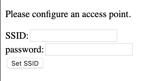
The HTML snippet that implements this interface is shown below.
requestPageSSID() {
    let ssid = (stored_ssid === undefined) ? "" : stored_ssid;
    return `<html><head><title><${HTML_TITLE}></title></head><body>
<h2>Access Point</h2>
<form action="/set-ssid" method="post">
<div><label name="ssid">SSID: </label><input type="text" id="ssid" name="ssid" value="${ssid}"><p><label name="password">Password: </label><input type="password" id="password" name="password" minlength="8"><p></div>
<div class="button"><button>Set SSID</button></div></form>`;
}
The server is created in configServer():
configServer() {
    this.apServer  = new Server();
    this.apServer.owner = this;
    this.apServer.callback = function(message, value, v2) {
        switch (message) {
            ...
When the request is complete, we parse out the post data to userReq so we can use it later.
case Server.requestComplete:
 let postData = value.split("&");
 for (let i=0; i<postData.length; i++) {
     let x = postData[i].split("=");
         this.userReq[x[0]] = x[1].replace("+"," ");
 }
 break;
Next, we set up the proper response to a request.
case Server.prepareResponse:
    let msg;
    if (this.path == "/set-ssid") {
        if (this.userReq.ssid)
            msg = this.server.owner.responsePageSSID(this.userReq);
    }
    else {
        if (this.server.owner.usingAP)
            msg = this.server.owner.requestPageSSID();
        else
            msg = this.server.owner.requestPage();
    }

    return {headers: ["Content-type", "text/html"], body: msg};
    break;
When the Set SSID button is pressed in the browser, the SSID and password are sent to the server. The clock saves the SSID and password as preferences that persist between runs of the application using the Preference class. Then it calls the doRestart function to restart the device.
case Server.responseComplete:
    if (this.path == "/set-ssid" && undefined !== this.userReq) {
        if (undefined !== this.userReq.ssid) {
            Preference.set(PREF_WIFI, "ssid", this.userReq.ssid);
            Preference.set(PREF_WIFI, "password", this.userReq.password);
            doRestart();
        }
    }
    break;
The clock saves the SSID and password so the user doesn't have to reconfigure Wi-Fi settings each time the clock reboots. Instead, the clock checks for saved credentials when it restarts.
In the clock's constructor, if there is no SSID or it is blank, the clock operates as a Wi-Fi access point so the user can configure Wi-Fi. Otherwise, the clock tries to connect to the internet using the stored credentials.
if (undefined === this.dict.ssid || '' === this.dict.ssid) {
    this.configAP(AP_NAME, AP_PASSWORD);
}
else {
    Timer.set(id => { this.checkConnected(); }, 10000);
    this.doWiFiScan(this.dict.ssid);
}
Connecting to the Internet
The doWiFiScan function scans for available Wi-Fi access points and sets up a timer to fall back to starting the Wi-Fi access point if it can not connect.
doWiFiScan(ssid="") {
    WiFi.scan({wantedSSID:ssid}, item => {
        if (item) {
            let theap = accessPointList.find(x => x.ssid === item.ssid);
            if (undefined === theap)
                accessPointList.push(item);
            else
                theap.rssi = item.rssi;

            if (item.ssid == this.wantedSSID)
                this.checkSSIDs();
        }
    });
}
In doWiFiScan, I add newly found access points to a global accessPointList. If one matches the desired SSID, then we'll try to connect to it in checkSSIDs().
checkSSIDs() {
    let theap = accessPointList.find(x => x.ssid === this.dict.ssid);
    if (undefined !== theap)
        this.connect(this.dict.ssid, this.dict.password);
    else {
        if (WiFi.status === 0) {            // idle
            if (this.wifiScans++ > MAX_WIFI_SCANS) {
                this.wifiScans = 0;
                this.checkConnected();
            }
            else
                this.doWiFiScan(this.dict.ssid);
        }
    }
}
checkSSIDs() also contains logic to rescan for Wi-Fi access points and fall back to creating its own access point if it can not connect.
Advertising the Server with mDNS
To simplify the Wi-Fi configuration process further, the clock uses mDNS to advertise the server. The hostname for the mDNS instance is "clock". This makes it possible for the user to access the HTTP server using the address http://clock.local, which is easier to type and remember than 192.168.1.4 or some other seemingly random IP address.
advertiseServer() {
    this.mdns = new MDNS({hostName: this.dict.name}, function(message, value) {
        if (1 === message) {
            if ('' != value && undefined !== this.owner) {
                this.owner.name = value;
            }
        }
    });
    this.mdns.owner = this;
}
Browser-based clock configuration
There are many ways to enable wireless communication with IoT devices. For example, the Moddable SDK supports a variety of networking protocols and BLE.
The clock provides a browser-based interface to configure the color and animation effects of the clock as well as the timezone, daylight-savings time adjustment and name. The screenshot below shows the clock style settings. The complete setup document describes all the available settings.
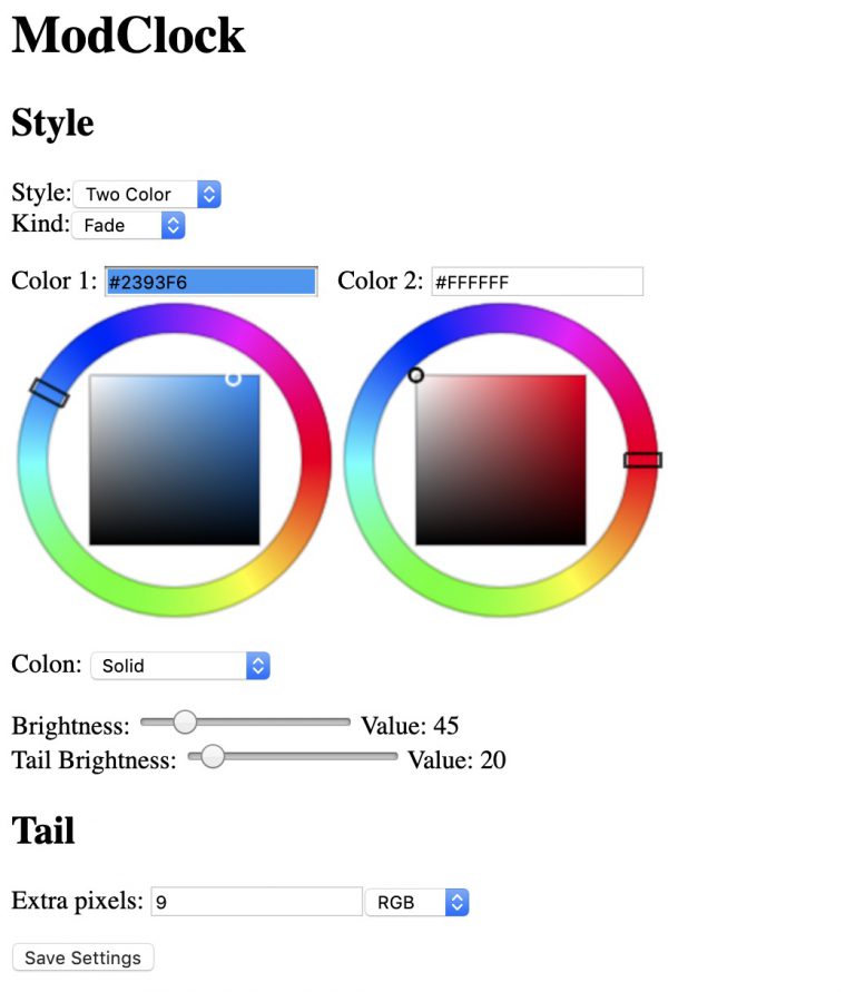
The configuration webpage can be accessed using the URL http://clock.local unless you've changed the clock's name whereupon it will be accessed by the URL http://**name**.local
Descriptions of the all of settings are described in this document.
OTA Updates
Everyone wants new features. Even with well-designed and tested software, there are always bugs to fix and improvements to be made.
Since the clocks I've made may go to places where I never see them again, it is unlikely that I'll be able to connect a USB cable to update them. The clock is also sealed into a box so it is troublesome to update even with physical access to the device.
The Moddable SDK contains a module to install OTA updates. With that, I can store a firmware image on a remote server so that the software on the clock can be updated at the push of a button on the web interface.
The next sections explain how to prepare the ESP32 to receive OTA updates.
Partition Map
You will need to partition the ROM to have space for the running image as well as the image that you are downloading.
The following partition map has two one-megabyte partitions allocated for that purpose: ota_0 and ota_1. There are also a small partitions for the OTA updater mechanism, otadata, and other Moddable partitions.
Create a partitions.csv file in a directory sdkconfig in your project containing:
nvs,      data, nvs,     0x009000, 0x4000,
otadata,  data, ota,     0x00d000, 0x2000,
phy_init, data, phy,     0x00f000, 0x1000,
ota_0,    app,  ota_0,   0x010000, 0x100000,
ota_1,    app,  ota_1,   0x110000, 0x100000,
xs,       0x40, 1,       0x210000, 0x010000,
settings, data, 1,       0x220000, 0x010000
In the manifest.json file, set the path of the new partitions file:
"build": {
    "PARTITIONS_FILE": "$(MYPROJECTPATH)/sdkconfig/partitions.csv"
},
Erase the whole device after changing the partition information.
esptool.py --port=/dev/cu.SLAB_USBtoUART erase_flash
Please Note
After doing the first OTA update, the bootloader will boot from the second ota partition (ota_1). That is the partition with the newly downloaded software. It will continue to use this partition until you do another OTA update, whereupon the new software will be loaded into the first ota partition (ota_0).
When you upload new software using the Moddable SDK over USB, it will be loaded into the first partition (ota_0). If the bootloader is still pointing to the second ota partition, then it will not run your uploaded software.
Erase the device if this happens. This will reset the bootloader to load from the first ota partition.
Alternately, to retain the preferences saved to the clock, erase only the otadata partition using the following command:
esptool.py --port /dev/cu.SLAB_USBtoUART erase_region 0xd000 0x2000
Triggering an OTA Update
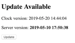
A simple way to trigger an OTA update is through an HTTP request to a server hosted by the ESP32. In the clock application, there is a button on the configuration webpage that triggers the OTA update process by sending a request to the path /checkForUpdate.
When the server receives a request with the path /checkForUpdate, it creates a new OTARequest object. OTARequest extends the HTTP Request object and makes a request to a remote cloud server for a new firmware file.
if (this.path == "/checkForUpdate") {
   clock.ota = new OTARequest(UPDATE_URL);
   clock.ota.onFinished = restart;
   clock.currentStyle = clock.styles[0];           // change to default style to indicate updating
}
The OTARequest class handles the response to the request and consumes the data.
class OTARequest extends Request {
    ...
    callback(message, value, v2) {
        switch (message) {
            case Request.status:
                if (200 !== value) {
                    trace(`Error, unexpected HTTP response ${value}\n`);
                    this.close();
                    if (this.ota) this.ota.cancel();
                }
                break;
We'll look for the content-length response header to see how large the firmware file is.
case Request.header:
    if ("content-length" === value) {
        this.length = parseInt(v2);
        trace(`Content-Length ${this.length}\n`);
    }
    break;
If the requested file exists, we make a new OTA object to handle the update.
case Request.headerComplete:
    if (!this.length) {
        trace(`Error: no Content-Length\n`);
        this.close();
    }
    this.ota = new OTA;
    break;
Then we'll read the response content from the update web server and write it to the OTA module.
case Request.responseFragment:
    let bytes = this.read(ArrayBuffer);

    this.received += bytes.byteLength;
    this.ota.write(bytes);
    trace(`received ${bytes.byteLength}:${this.received} of ${this.length}\n`);
    break;
When the transfer is complete, we let the OTA module complete the update. Then we restart the ESP32 in the onFinished() callback when the update has completed.
case Request.responseComplete:
    trace("received complete\n");
    this.ota.complete();
    if (undefined !== this.onFinished)
        this.onFinished();
    break;
NeoPixels Enhancements
Moddable's original implementation of NeoPixels worked well with short strings of pixels. Longer strings would occasionally flicker or blink a random color. Apparently this is due to the Wi-Fi stack interfering with the timing of the RMT driver.
The NeoPixels driver has been updated with the option to use the second processor in the ESP32 to service the NeoPixels. By default, the NeoPixels driver uses the ESP32's RMT driver. Configuring Moddable to use the new NeoPixels driver takes a few steps:
-
Copy the sdkconfig.defaults file from $MODDABLE/build/devices/esp32/xsProj to a new sdkconfig directory in your project. You can do this from the terminal using the following commands (replace $MYPROJECTPATH with your project's path):
cd $MYPROJECTPATH
mkdir sdkconfig
cp $MODDABLE/build/devices/esp32/xsProj/sdkconfig.defaults* sdkconfig
-
Add a build object in your manifest.json file to use your sdkconfig.
"build": {
     "SDKCONFIGPATH": "$(MYPROJECTPATH)/sdkconfig"
},
-
Also add a defines object to the manifest to use the new driver.
"platforms": {
    "esp32": {
        "defines": {
            "neopixel": {
                "custom_rmt_driver": 1
            }
        }
    }
}
-
Make the following changes to sdkconfig.defaults and sdkconfig.defaults.release. That is, if the parameter exists, change it to match, or add the parameter to the bottom of the file:
CONFIG_FREE_RTOS_UNICORE=
CONFIG_ESP32_WIFI_TASK_PINNED_TO_CORE_0=y
CONFIG_ESP32_WIFI_TAKS_PINNED_TO_CORE_1=
Watchdog
A clock runs all the time. NeoPixels retain their state, so if the ESP32 crashes or hangs, there is no indication of that on the display, except that the time and visual effect doesn't change. This can lead to problems.
We use the ESP32's watchdog timer (WDT) to monitor the state of the app and reboot if it notices a hang.
In the sdkconfig.defaults.release file, add the following:
CONFIG_INT_WDT=y
CONFIG_INT_WDT_TIMEOUT_MS=300
CONFIG_INT_WDT_CHECK_CPU1=y
CONFIG_TASK_WDT=y
CONFIG_TASK_WDT_PANIC=y
CONFIG_TASK_WDT_TIMEOUT_S=10
CONFIG_TASK_WDT_CHECK_IDLE_TASK_CPU0=y
CONFIG_TASK_WDT_CHECK_IDLE_TASK_CPU1=y
This will turn on the WDT for interrupts at 300ms (CONFIG_INT_WDT_TIMEOUT_MS=300), and for tasks at a 10 second interval (CONFIG_TASK_WDT_TIMEOUT_S=10). If the watchdog timer isn't reset within these time intervals, it will cause a silent reboot (CONFIG_ESP32_PANIC_SILENT_REBOOT=y).
Conclusion
The large bright clock was greatly appreciated by my family and friends. The project turned into an exploration of some of product-ready features of the Moddable SDK such as OTA updates and flexible Wi-Fi configuration to improve the ease of use and reliability of the clock.
From the large number of modules in the Moddable SDK, I can imagine a number of improvements and additions that could be made to the clock. An I2C real-time clock module would allow the clock to be used where Wi-Fi is unavailable. Environmental sensor modules could be added to send data to the cloud and display time/temperature on the clock. An audio module or buzzer could provide the alarm for an alarm clock. Let us know your ideas.
Assembly instructions for the clock can be found here.