Copyright 2016-2020 Moddable Tech, Inc.
Revised: December 1, 2020
This document describes how to set up and build Moddable applications for the Qualcomm QCA4020 series processors.

The Qualcomm QCA4020 is an low-powered ARM-based SoC with Bluetooth and Wi-Fi support.
A Qualcomm Developer Network account is required to download the Qualcomm QCA4020 SDK. Moddable supports SDK version 3.x.
Moddable supports FreeRTOS on the QCA4020 Customer Development Board (CDB) using a Linux host build platform.
The build platform -p qca4020/cdb is used to target the CDB development board powered by the QCA4020.
After the initial host setup, there are four major steps to build and deploy a Moddable application for the QCA4020.
-
The application, assets, modules and XS runtime are built into an archive using the mcconfig tool. This produces a xs_qca4020.a archive file.
-
Build the small launcher application which includes the xs_qca4020.a archive and the Qualcomm libraries.
-
Flash the application to the board.
-
Use gdb to launch and debug the native portion of your application. Use xsbug to debug your ECMAScript application.
The Moddable SDK has been tested on 16.04 LTS (64-bit), 18.04.1 (64-bit) and Raspberry Pi Desktop (32-bit) operating systems. These setup instructions assume that a host GCC toolchain has already been installed.
Set up the Linux environment as described in the Moddable SDK - Getting Started guide.
Download the Qualcomm QCA4020 SDK version 3.0 from the Qualcomm Developer Network's Tools & Resources - QCA4020 page.
Decompress the SDK file into a ~/qualcomm directory making:
/home/<user>/qualcomm/qca4020
The qca4020 directory should contain a target/ subdirectory.
Export required build environment variables:
export SDK=/home/<user>/qualcomm/qca4020/target
export CHIPSET_VARIANT=qca4020
export RTOS=freertos
export BOARD_VARIANT=cdb
export QCA_GCC_ROOT=/usr/local/bin/gcc-arm-none-eabi-6-2017-q2-update
Update the PATH environment variable to include the SDK cortex-m4 target directory:
export PATH=$PATH:$SDK/bin/cortex-m4
Download version 6.2 (Linux, 64-bit) of the GNU embedded toolchain for ARM-based processors from the Arm Developer Site
Update the PATH environment variable to include the toolchain installation path:
export PATH=$PATH:/usr/local/bin/gcc-arm-none-eabi-6-2017-q2-update/bin/
Ref: B Development Kit User Guide - section 3.2
Download FreeRTOS:
cd ~/qualcomm
git clone https://source.codeaurora.org/external/quartz/FreeRTOS
cd FreeRTOS
git checkout v8.2.1
Download the QuRT RTOS abstraction layer:
cd ~/qualcomm
git clone https://source.codeaurora.org/external/quartz/ioe/qurt
Note: You may get an warning here. Continue.
cd qurt
git checkout v2.0
The FreeRTOS configuration file is located here:
~/qualcomm/FreeRTOS/1.0/FreeRTOS/Demo/QUARTZ/FreeRTOSConfig.h
Change the following config values:
#define configTICK_RATE_HZ        ( ( TickType_t )  1000)
#define configTOTAL_HEAP_SIZE     ( ( size_t ) 0x13000) )
Note: If you change the configTOTAL_HEAP_SIZE , you will need to change RTOS_HEAP_SIZE in the DefaultTemplateLinkerScript.ld as described below. You will also need to rebuild qurt and FreeRTOS and copy them into the proper place, also described below.
To assist in development, you may want to enable two additional configuration values to trigger 'C' callbacks for stack overflow and out of memory conditions.
To trigger the vApplicationStackOverflowHook() callback in $MODDABLE/build/devices/qca4020/xsProj/src/main.c on a stack overflow, change the following config value:
#define configCHECK_FOR_STACK_OVERFLOW 2
To trigger the vApplicationMallocFailedHook() callback when memory allocation fails, change the following config value:
#define configUSE_MALLOC_FAILED_HOOK 1
Ref: B Development Kit User Guide - section 3.8
Build the QuRT RTOS abstraction layer and copy the libraries into place:
cd ~/qualcomm/qurt/FreeRTOS/2.0
make all
cp output/qurt*.lib ~/qualcomm/qca4020/target/lib/cortex-m4IPT/freertos/
Build the FreeRTOS library and copy into place:
cd ~/qualcomm/FreeRTOS/1.0/FreeRTOS/Demo/QUARTZ
make all
cp output/free_rtos.lib ~/qualcomm/qca4020/target/lib/cortex-m4IPT/freertos/
Ref: B Development Kit User Guide - section 3.7.2.1
OpenOCD is used to flash the binary to the QCA4020.
Download openocd-0.10.0 and build with the --enable-ftdi option. The location doesn't matter.
cd open-ocd-0.10.0
./configure --enable-ftdi
make install
Note: If there is an error libusb-1.x not found... install the libusb-dev package.
sudo apt-get install libusb-1.0-0.dev
Ref: B Development Kit User Guide - section 3.7.2 (JTAG debug mode)
Make sure system sleep is disabled so that JTAG can connect on boot:
In the file $MODDABLE/build/devices/qca4020/xsProj/src/export/DevCfg_master_devcfg_out_cdb.xml change:
<driver name="Sleep"> ...
	<props id="0x2" oem_configurable="false" type="0x00000002"> 1 </props>
to:
<props ... > 0 </props>
Disable the watchdog so the application doesn't terminate in err_jettison_core while using xsbug. Same file as above:
Change:
<props name="dog_hal_disable" type="0x00000002”> 0 </props>
to:
<props name="dog_hal_disable" type="0x00000002”> 1 </props>
Note: you will want to re-enable the watchdog before shipping.
The link map specifies where in memory the different components of your application will go.
The QCA4020 allocates RAM to read-only memory (instructions and data), and read-write memory for each of the different operating modes of the chip. Moddable apps run primarily in the Full Operating Mode (FOM).
The QCA4020 also has flash memory that can be used to store data and code. Moddable stores resources, XS bytecode and static variables in flash. Application object code runs out of execute-in-place (XIP) memory.
We adjust link map values to give us more data space in RAM, and to move read-only data to flash.
In the file MODDABLE/build/devices/qca4020/xsProj/src/export/DevCfg_master_devcfg_out_cdb.xml change the following:
Disable DEP (data execution prevention) by setting the property value to 0:
<props id="1" id_name="PLATFORM DEP ENABLE" oem_configurable="true" helptext="Enable or disable data execution prevention." type="0x00000002">
	0
</props>
Disabling DEP allows more RAM to be allocated by applications.
In the file ~/qualcomm/qca4020/target/bin/cortex-m4/freertos/DefaultTemplateLinkerScript.ld do the following:
Make sure RTOS_HEAP_SIZE has the same value as the define configTOTAL_HEAP_SIZE in FreeRTOSConfig.h described above.
RTOS_HEAP_SIZE = 0x13000;
Note: When configUSE_MALLOC_FAILED_HOOK is defined in FreeRTOSConfig.h, the vApplicationMallocFailedHook() error handler is invoked. This can be used to determine if you need to allocate more memory to the FreeRTOS heap.
vApplicationMallocFailedHook() is found in $MODDABLE/build/devices/qca4020/xsProj/src/main.c
Move your application's static data into flash (XIP):
XIP_OEM_RO_REGION :
{
	*(XIP_OEM_RO_SECTION)
After this, add:
	*(.flash*)
	*(.flash.rodata*)
Ref: (see similar in Document C: QCA402x (CDB2x) Programmers Guide - section 4.3.4 Resize application memory)
Change the RAM_FOM_APPS_RO_MEMORY and RAM_FOM_APPS_DATA_MEMORY origin and length values:
RAM_FOM_APPS_RO_MEMORY   (RX) : ORIGIN = 0x10046000, LENGTH = 0x0a000
RAM_FOM_APPS_DATA_MEMORY (W)  : ORIGIN = 0x10050000, LENGTH = 0x40000
If you encounter stack overflows, the stack size of the XS task can be increased by changing xsMain_THREAD_STACK_SIZE in $MODDABLE/build/devices/qca4020/base/xsmain.c.
Note: When configCHECK_FOR_STACK_OVERFLOW is set to 2 in FreeRTOSConfig.h, the vApplicationStackOverflowHook() error handler is invoked.
vApplicationStackOverflowHook() is found in $MODDABLE/build/devices/qca4020/xsProj/src/main.c
Build Moddable tools for Linux (if you haven't already):
cd $MODDABLE/build/makefiles/lin
make
Build the Moddable helloworld app:
cd $MODDABLE/examples/helloworld
mcconfig -d -m -p qca4020/cdb
The mcconfig tool builds the application and generates the xs_qca4020.a archive, which contains the app, any assets and the XS runtime.
You will need to set some environment variables to configure the stub application build:
export APP_NAME=helloworld
export DEBUG=1
Note: The APP_NAME environment variable value must match the name of the application being built.
Build the stub application to link in the qca4020 libraries and main.c.
cd $MODDABLE/build/devices/qca4020/xsProj/build/gcc
make
Ref: B Development Kit User Guide - section 3.6 (Linux Flash)
Note: Flashing takes a long time (over 3 minutes running Ubuntu in a MacOS VirtualBox) with a lot of output on the console.
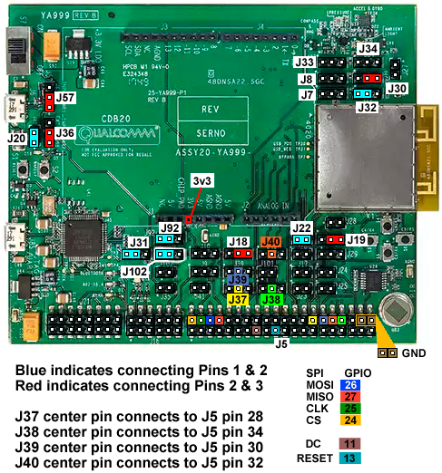
Make sure jumper is on J31 1&2 and reset the board. If J31 is removed, the board will boot directly into the app.
Pin Configuration for JTAG GPIO 53:50

To use JTAG3 (which doesn't conflict with SPI):

// JTAG bootstrap
J30 Connect pins 2 and 3 for JTAG    (GPIO_25 low)
J32 Connect pins 1 and 2 for JTAG    (GPIO_18 high)

// JTAG
J37 pin 2 Connect J5 pin 28 (JTAG TCK)
J38 pin 2 Connect J5 pin 34 (JTAG TDI)
J39 pin 2 Connect J5 pin 30 (JTAG TDO)
J40 pin 2 Connect J5 pin 32 (JTAG TMS)
The development board should be connected and powered on. The lower USB port is used to connect to Linux.
Note: When you plug in the cdb board, two USB devices will be made available to Linux: /dev/ttyUSB0 and /dev/ttyUSB1. The first will be captured by OpenOCD and /dev/ttyUSB1 will be used to connect to xsbug.
Navigate to the project build directory and run the flash tool:
cd $MODDABLE/build/devices/qca4020/xsProj/build/gcc
sh flash_openocd.sh
Note: the flash tool launches openocd and leaves it running. This is helpful as we will need it running later for gdb.
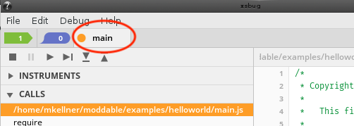
In another terminal window, launch xsbug and serial2xsbug:
xsbug &
serial2xsbug /dev/ttyUSB1 115200 8N1
xsbug is used to debug the ECMAScript side of your application. serial2xsbug provides a serial to network socket bridge between the QCA4020 CDB and the xsbug debugger.
Navigate to the project build directory and launch gdb:
cd $MODDABLE/build/devices/qca4020/xsProj/build/gcc
arm-none-eabi-gdb -x v2/quartzcdb.gdbinit
gdb is used to debug the native 'C' portion of your application.
A considerable amount of output will appear on the screen. At the (gdb) prompt type c to continue three times to launch the app. You can also set breakpoints, view source and variables, etc...
xsbug will show the connection is made and the application should start.
You can now run and debug your application.
If you would like to boot directly to your application without having to launch and use gdb:
Disconnect jumper on J31 between pins 1 & 2 and reset the board.
The board will boot into the app instead of waiting for gdb.
Note: if you have a debug build, your application will still try to connect to xsbug at startup. If it cannot connect, it will proceed to launch. You can continue to debug your application without using gdb.
	alias killocd='killall openocd'
	alias doocd='killall openocd; openocd -f qca402x_openocd.cfg'
	alias dogdb='arm-none-eabi-gdb -x v2/quartzcdb.gdbinit'
-
You will need to restart serial2xsbug if you disconnect the board or shut down the virtual usb interface.
-
When the device crashes and you want to restart your debug session, you will need to restart gdb.
- You may also need to kill and restart openocd
killall openocd; openocd -f qca402x_openocd.cfg
-
Press the Reset button (near J20) before reflashing.
-
The upper USB port near the switch is for Windows connection. Do not use this port with a Linux Host.
-
The lower USB port provides JTAG connection (/dev/ttyUSB0 for JTAG and /dev/ttyUSB1 for serial output (and xsbug)
The following pinout table and image describe the connections required to support a SPI display on the CDB20 board.
| Screen pin |
CDB20 header / pin number |
GPIO |
SDO (MISO) |
J5 / 8 |
27 |
LED (3.3V) |
J1 / 4 |
N/A |
SCK (CLK) |
J5 / 4 |
25 |
SDI (MOSI) |
J5 / 6 |
26 |
RESET |
J1 / 4 |
N/A |
CS |
J5 / 2 |
24 |
DC |
J5 / 15 |
11 |
GND |
J5 / 40 |
N/A |
VCC |
J1 / 4 |
N/A |

Documentation for the QCA4020 can be found on the Qualcomm Developer Network. You will need to be logged in to access these files.
Of particular interest and referenced earlier in this document are:
A QAPI Specification
Contains the API Documentation
B Development Kit User Guide
Describes setting up the SDK, development environment, how to flash and debug. Also describes board jumper settings.
C QCA402x (CDB2x) Programmers Guide
Contains an overview, networking features, programming model, memory model, etc. GPIO configuration and interfaces
Qualcomm Developer Network
QCA4020 SDK v3
QCA4020 Tools
Arm Developer GNU-ARM Downloads
gcc-arm-none-eabi version 6.2 (Linux, 64-bit)
Moddable Getting Started Guide